Action of commutator
The ends of Armature winding are connected to Commutator which is connected to brushes which are then connected to Supply or Load. Commutator is also called as Slip Rings.
It performs two important functions:
- Convert alternating quantities to direct quantities and vice versa.
- Keep rotor or armature MMF stationary in space.

- One copper ring is split into 2 parts insulated from each other and also from the shaft on which it is mounted.
- Coils ends are connected to copper segments on which two carbon brushes are resting.
- Alternating emf is generated in N-turn coil, which is converted from ac to dc by commutator.
When armature conductors are rotated in the influence of Stator Magnetic Field then there is a relative motion between the conductors and field and hence there is a dynamically induced emf in the conductors. This is working principal of DC generator. The dynamic emf induced in any moving conductor is given by:
→ →
E = I( V ✕ B )
Where V is relative velocity between field and conductor and B is the magnetic flux density.
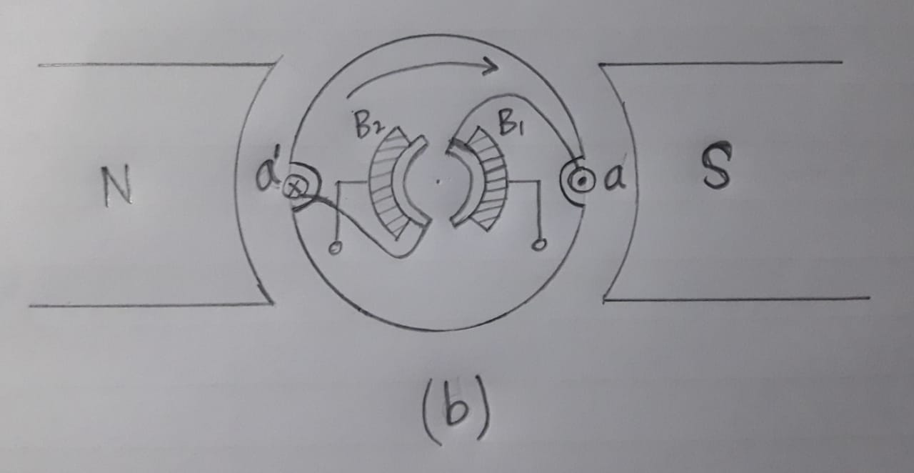
The schematics shown below show how emf is induced in coils as they rotate under the influence of Stator field.

In position (a), emf induced is zero since instantaneous direction of rotation of coil aa' is parallel to magnetic field.
After 90° rotation in position (b) the coils settle under North pole and South pole and by Lenz Law the induced emf has polarity as shown.
In position (c) again induced emf is zero as instantaneous direction of rotation of coil aa' is anti-parallel to magnetic field.

In position (d) again emf is induced as direction of rotation is perpendicular to magnetic field.

If we consider dot as positive emf and cross as negative emf then emf induced in coil aa' is positive for half cycle and negative for another half.
But the brush B1 is always connected to conductor which carries dot current and brush B2 is connected to conductor which carries cross current. So, the voltage induced across the brushes does not change in polarity though the voltage is alternating in individual conductors. This is how commutator converts AC into DC for generator and vice versa for motor.

Field MMF is stationary, armature MMF must also be stationary for production of electromagnetic torque. This center line of poles around which field coils is wound is called direct axis of dc machine. In the above example that axis is horizontal as field poles are shown in horizontal position.
By Right Hand Rule if we determine the direction of magnetic field produced by armature winding, it comes downwards that is perpendicular to the d-axis and as q-axis. The magnitude of magnetic field is pulsating but direction is constant so Armature MMF remains stationary in space. So second function of commutator is also completed.
The coils when they are short circuited lie along q-axis so we represent brushes along q-axis.
Hence DC Machine can be represented in circuit as below :

When the coils are short circuited and then current is reversed in the coil, this process is called Commutation. The instant of Commutation is the time at which the coils are short circuited and we want that emf induced in short circuited coils at instant of commutation should be zero so that zero current flows and if this emf is non-zero, it can result in high current which can lead to sparking at commutator. So, it is always desirable that coils undergoing commutation should lie along MNA ( Magnetic Neutral Axis ) that is perpendicular to magnetic field so that zero emf is induced at the time of commutation.
Comments
Post a Comment